
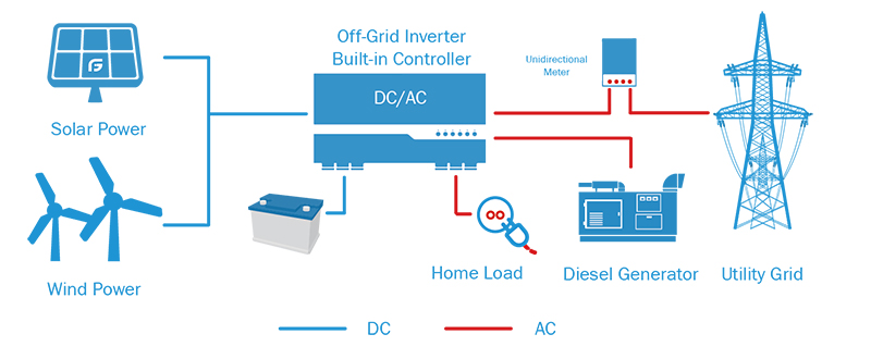
Off-grid system, also known as an independent solar power generation system, is a system that does not rely on the grid and operates independently. It mainly consists of solar panels, energy storage batteries, charge and discharge controllers, inverters, and other components. The electricity generated by the solar panel flows directly into the battery and is stored. When it is necessary to supply power to the electrical appliances, the DC in the battery is converted into 220V AC power through the inverter.
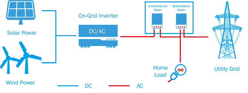
Grid-connected system means that solar power generation, home power grid, and public power grid are connected. Solar power generation is directly inverted into the required parallel power voltage required by the national power grid and is given priority for household use. When solar power generation exceeds the use of household appliances When the amount of electricity is low, the surplus electricity is transmitted to the public grid; and when the solar power generation capacity can not meet the use of household appliances, it will automatically be replenished from the grid.
Off-grid systems must be equipped with batteries.
No battery required for on-grid systems.
Third, the application is different.
The off-grid system is not restricted by region and is widely used. It can be installed and used as long as there is sunlight. Therefore, it is very suitable for remote areas without power grids, isolated islands, fishing boats, outdoor breeding bases, etc., and can also be used as frequent power outages. Emergency power generation equipment in the region.
The on-grid system saves the cost of the system because it can eliminate the use of battery cells. Therefore, if you want to save electricity costs and provide a convenient power supply, you can choose an on-grid solar power system, which is the mainstream method at present and in the future.
The design idea of the battery is to ensure that the load can still work normally when the sunlight is continuously lower than the average value. We can imagine that the battery is fully charged. Under what types of situations are there in systems with lower than average illuminance, the electrical energy generated by the solar cell components cannot be filled, and a vacancy is created due to the load-consuming energy from the battery. At the end of the day, the battery is not fully charged. If the illuminance is still lower than the average the next day, the battery still has to be discharged to meet the needs of the load, and the state of charge of the battery continues to decrease. Maybe the same thing will happen on the third and fourth days. To avoid damage to the battery, such a discharge process can only be allowed to continue for a certain period until the state of charge of the battery reaches the specified dangerous value. To quantitatively evaluate the situation that the sun's illumination is continuously lower than the average value when designing the battery, we need to introduce an indispensable parameter: the number of self-sufficient days, that is, the system can still work normally without any external energy. The number of days, this parameter is for the system designer to choose the battery capacity required to use.
Generally speaking, the determination of the number of self-sufficiency days is related to two factors: the requirement for the power supply; the meteorological at the photovoltaic system installation site, battery and other conditions, that is, the maximum number of continuous rainy days. Generally, the maximum number of continuous cloudy and rainy days in the photovoltaic installation site can be compared with photovoltaic system batteries as the number of self-sufficient days used in the system design, while comprehensively considering the requirements of the load on the power supply.
For photovoltaic applications where the load is not very demanding on the power supply, we usually take the number of self-supply days as 3-5 days in the design; for the photovoltaic application where the load requirements are very strict, we usually take the number of self-supply days as 7-14 days. The so-called system with less stringent load requirements usually means that the user can adjust the load demand slightly to adapt to the inconvenience caused by bad weather; while the strict system refers to the more important power load, such as communication, navigation, or important health facilities: hospitals, clinics, etc. In addition, the installation location of the photovoltaic system must also be considered. If it is in a remote area, a larger battery capacity must be designed because it takes a long time for maintenance personnel to arrive on site.
The batteries used in photovoltaic systems include nickel-metal hydride batteries, nickel-cadmium batteries, lead-acid batteries and lithium battery, but in larger systems, taking into account factors such as technological maturity and cost, we use lithium batteries. In the following content, the storage batteries that are not specifically mentioned refer to lithium iron phosphate(LiFePO4) batteries.
The design of the battery includes the design calculation of the battery capacity and the series and parallel design of the battery pack. The following describes the basic method of calculating battery capacity:
The first step is to multiply the daily power consumption required by the load by the number of self-sufficient days determined according to the actual situation to obtain the preliminary battery capacity.
The second step is to divide the battery capacity obtained in the first step by the maximum allowable depth of discharge of the battery. Because the battery cannot be completely discharged on self-sufficient days, it is necessary to divide by the maximum depth of discharge to get the required battery capacity. The selection of the maximum depth of discharge needs to refer to the performance parameters of the battery selected in the photovoltaic system, and you can obtain detailed information about the maximum depth of discharge of the battery from the battery supplier. Under normal circumstances, if you are using a deep cycle battery, it is recommended to use an 80% depth of discharge (DOD); if you are using a shallow cycle battery, it is recommended to use a 50% depth of discharge (DOD). The basic formula for designing battery capacity is as follows:
Battery capacity = (self-sufficient days × daily average load) / maximum depth of discharge
Below we introduce the method to determine the battery series and parallel. Each battery has its nominal voltage. To reach the nominal voltage of the load, we connect the batteries in series to supply power to the load. The number of batteries that need to be connected in series is equal to the nominal voltage of the load divided by the nominal voltage of the battery.
Number of batteries in series = Nominal voltage of load/Nominal voltage of the battery
To illustrate the application of the above basic formula, we use a small AC photovoltaic application system as an example. Assuming that the power consumption of the AC load of the photovoltaic system is 10kWh/d, if the efficiency of the inverter we choose to use is 90% and the input voltage is 24V, then the required DC load is 462.96Ah /d(10000Wh/d÷0.9÷24V≈462.96Ah/d). Assuming that the DC load is not very strict on the power requirements, then the user can adjust the power consumption according to the weather conditions more flexibly. If we choose 5 days of self-sufficiency and use deep-cycle batteries with a discharge depth of 80%, then:
Battery capacity=5d×462.96Ah/d÷0.8=2893.5Ah
If you choose a 12V, 400Ah battery, the number of batteries that need to be connected in series is:
Number of batteries in series=24V÷12V=2(pcs)
The number of batteries that are to be connected in parallel is:
Number of batteries in parallel=2893.5÷400≈7.23(pcs)
We take the integer as 8. The system needs to use 12V 400A.h batteries: 2 (series) × 8 (parallel) = 16 (pcs).
The following is an example of a pure DC system: the photovoltaic power supply system of a rural house is only used on weekends, and low-cost shallow-cycle batteries can be used to reduce system costs. A load of this country house is 90Ah/d, and the system voltage is 24V. We choose 2 days of self-sufficiency, and the maximum allowable depth of discharge of the battery is 80%, then:
Battery capacity=(2d×90)/0.8=225Ah
If you choose a 12V 100Ah battery, you need 2 (series) × 3 (parallel) = 6 batteries.
The above is only the basic estimation method of battery capacity. In practical applications, many performance parameters will affect the battery capacity and service life. To get the correct battery capacity design data, the above basic estimation method must be revised.
For a battery, its capacity is not static. The capacity of the battery is related to two important factors: the discharge rate of the battery and the ambient temperature.
The capacity of the battery changes with the change of the discharge rate. As the discharge rate decreases, the capacity of the battery will increase accordingly, which will have an impact on the design of the battery capacity. When designing a photovoltaic system, the battery capacity at an appropriate discharge rate should be selected for the designed system. Generally, the rated capacity of the battery provided by the manufacturer is the battery capacity at a discharge rate of 80%, but in a photovoltaic system, the energy stored by the battery is mainly to provide the load in the self-sufficient days, and the discharge rate is usually low.
The capacity of the battery will change as the ambient temperature changes. When the ambient temperature drops, the capacity of the battery will decrease. Generally, the capacity of LiFePO4 batteries is calibrated at 25°C. As the temperature decreases, the capacity at 0°C drops to approximately 90% of the rated capacity, and at -20°C it drops to approximately 80% of the rated capacity. Therefore, the influence of the battery's ambient temperature on its capacity must be considered.
If the temperature of the photovoltaic system installation site is very low, this means that the actual usable capacity of the battery capacity designed according to the rated capacity in the area will be reduced, that is, the power demand of the system load cannot be met, and it will be under actual working conditions. This leads to over-discharge of the battery, shortens the service life of the battery, and increases maintenance costs. In this way, the battery capacity required in the design is larger than the capacity calculated according to the battery parameters under the standard condition (25℃). Only by choosing more than the calculated capacity when installed relative to 25℃ can the battery be guaranteed to be at a temperature lower than 25℃. In the case of ℃, it can fully provide the required energy.
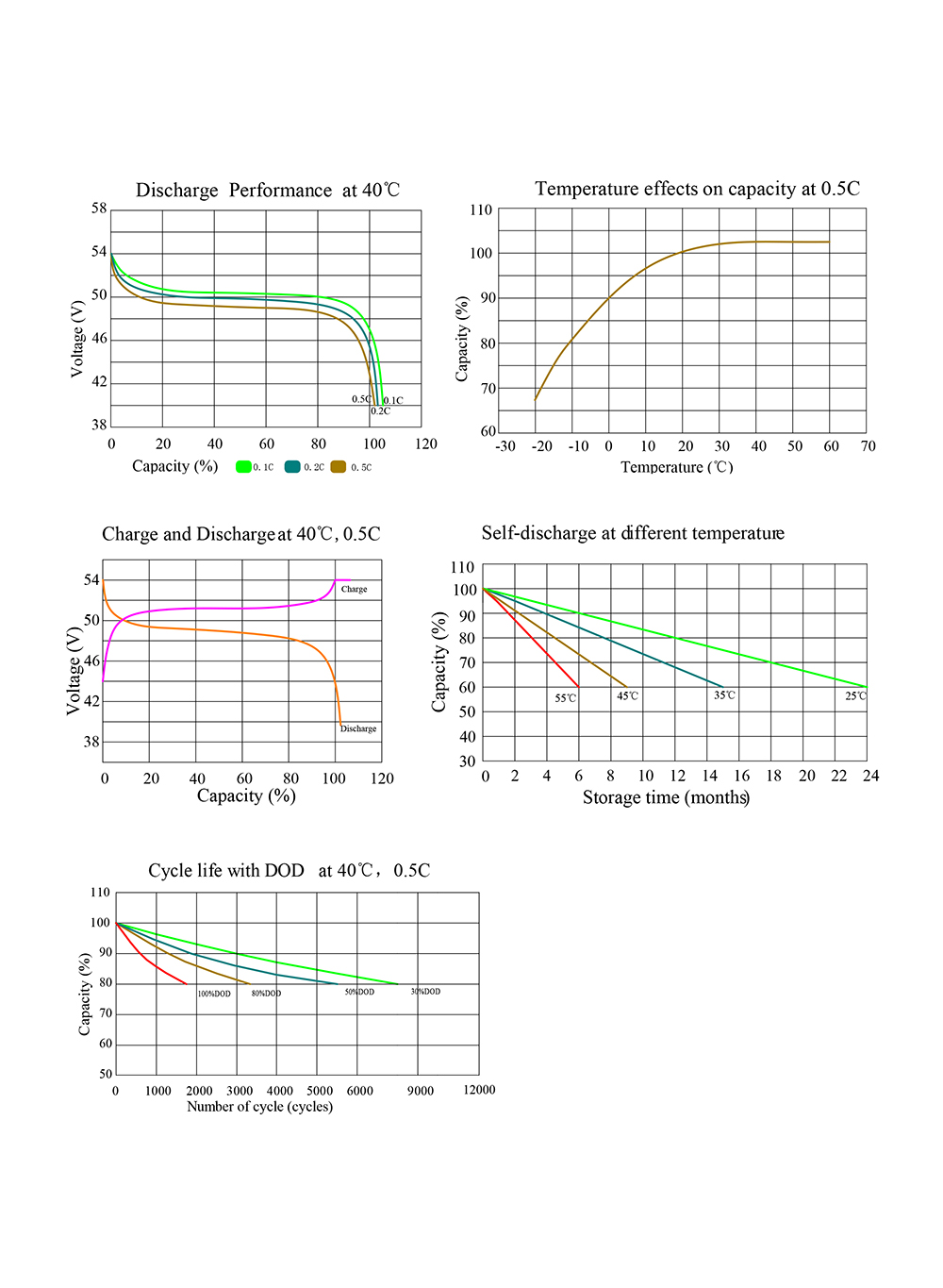
Figure 1: lifepo4 battery performance curve
Taking into account all the above calculation correction factors, we can get the final calculation formula of the battery capacity as follows:
Battery capacity (①designated discharge rate) = (self-sufficient days × daily average load) / maximum allowable discharge retention degree
The following analyzes the parameters in the formula:
(1) The maximum allowable depth of discharge. Generally speaking, the maximum allowable depth of discharge of shallow-cycle batteries is 50%, and the maximum allowable depth of discharge of deep-cycle batteries is 80%. If you are in a severe cold area, you must take into account the low-temperature antifreeze problem and make the necessary corrections. This value can be appropriately reduced during design to expand the capacity of the battery. Extend the service life of the battery. For example, if a deep-cycle battery is used, the maximum usable percentage of battery capacity is set at 60% instead of 80% when designing. This can increase the service life of the battery and reduce the maintenance cost of the battery system while reducing the initial cost of the system. There will be too much impact. According to the actual situation, this can also be handled flexibly.
(2) Temperature correction factor. When the temperature drops, the capacity of the battery will decrease. The function of the temperature correction factor is to ensure that the installed battery capacity is greater than the capacity calculated according to the 25℃ standard so that the designed battery capacity can meet the power demand of the actual load.
The following examples illustrate the application of the above formula. If a photovoltaic power supply system supplies power to a remote communication base station, the system has two loads: load one, working current is 10A, working 6 hours a day; load two, working current is 5A, working 8 hours a day. The 24h average minimum temperature of the location of the system is -20℃, and the self-sufficiency time of the system is 5d. Use deep-cycle industrial batteries (maximum DOD is 80%).
Because the 24h average minimum temperature in the area where the photovoltaic system is located is -20°C, the maximum allowable depth of discharge of the battery must be corrected. From the relationship between the maximum depth of discharge and the battery temperature, we can determine that the maximum allowable depth of discharge is 50%.
Weighted average load working time=(5A×8h+10A×6h)/(5A+10A)=6.67h
According to the previous typical temperature-discharge rate-capacity curve, the discharge rate closest to the calculated average discharge rate is 50h discharge rate, and the temperature correction coefficient corresponding to this discharge rate at -20°C is 0.7 (also can be based on the supply Query the performance table provided by the supplier). If the calculated discharge rate is between the two data, it is more reliable to choose a faster discharge rate (short time). So the battery capacity is:
Battery capacity=5×(5A×8h+10A×6h)/(0.5×0.7)≈1428.57Ah
According to the battery parameter table provided by the supplier, we can select suitable batteries for series and parallel connections to form the required battery pack.
After calculating the required battery capacity, the next step is to decide how many single batteries to choose in parallel to get the required battery capacity. There are many options for a single battery. If the calculated battery capacity is 500Ah, then we can choose one, 500Ah single battery, or two 250Ah batteries in parallel, or 5 100Ah battery connected in parallel. In theory, these options can meet the requirements, but in practical applications, the number of parallel connections should be minimized. In other words, it is best to choose a large-capacity battery to reduce the number of parallel connections required. The purpose of this is to minimize the impact caused by the imbalance between the batteries, because parallel batteries may cause mutual imbalance during charging and discharging. The more groups connected in parallel, the greater the possibility of battery imbalance. Generally speaking, it is recommended that the number of parallel connections should not exceed 4 batteries.
At present, many photovoltaic systems use two sets of parallel mode, so that if one set of batteries fails and cannot work normally, you can disconnect the set of batteries for maintenance, and use another set of batteries to work. Although the capacity drops, the system can also maintain normal operation under the nominal voltage. In short, the parallel design of battery packs needs to consider different actual conditions and make different choices according to different needs.
Contact: Sam
Phone: +8613076969720
Tel: +86-0755-86932475
Email: info@futonenergy.com
Add: Room 301, Building 24, Ailian Industrial Zone, Wulian Community, Longgang Street, Longgang District, Shenzhen 518116, Guangdong, China
We chat